
|
|
|
|
|
The engine used on the AH-1F helicopter is the T53-L-703. It is a free power turbine. What is a free power turbine engine? It is an engine that is made up of two rotating assemblies that are mechanically free of each other. What are the advantages of the free power turbine engines? It eliminates the use of heavy clutches and prevents rpm control problems that would exist if the engine engaged the transmission directly. The two rotating assemblies are known as the gas producer, sometimes referred to as the n1 or first stage, and the power turbine n2 or second stage. The symbol "n" refers to rotation (rpm) of the two independent stages. Actually the n1 and n2 components rotate in opposite directions and at different rpm.
What is the purpose of the gas producer? It produces all the gases and fuel for the engine operation. The power producer is driven by the hot gases as does the n1 assembly, but it supplies the power to drive the transmission, main and tail rotor.
In the designation, the T is for turbine, 53 for the military number, L for Lycoming (manufacture) and 703 stands for the modification series. The 703 is capable of producing 1485 shp (shaft horsepower). However, it has been limited to 1290 shp at 100% torque because of power train limitations.
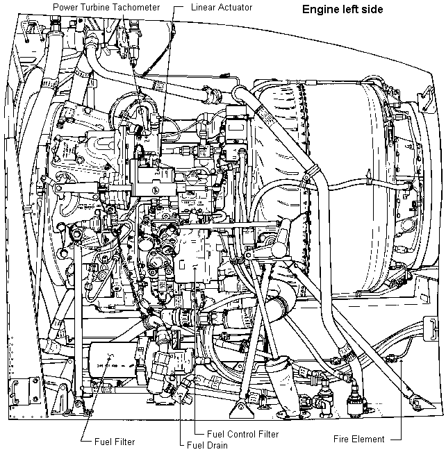
The power turbine (n2) tachometer generator operates engine scale on the dual tachometer.
Linear Actuator
The linear actuator located on the left side of engine is connected between the droop
compensator and the overspeed governor. It is powered by a 28 VDC motor which either
extends or retracts the actuator to control the n2 speed. Controlled by the
increase / decrease switch on the collective head or on the gunner's miscellaneous panel.
Fuel Filter
The fuel filter is located on the left hand side of the engine deck. Its purpose is to
filter fuel prior to entering the fuel control. A caution light on the instrument panel
informs the pilot when the filter becomes partially obstructed.
The fuel drain control is used by the pilot on preflight inspection to drain a few ounces of fuel in a clear jar. The pilot can then check to see for any contamination or water.
Fire Detection System
Provides visual indication of a fire in the engine compartment via the fire detector light
on the pilot's console. Sensing elements are attached to the tail rotor driveshaft tunnel,
fire wall and heatshield.
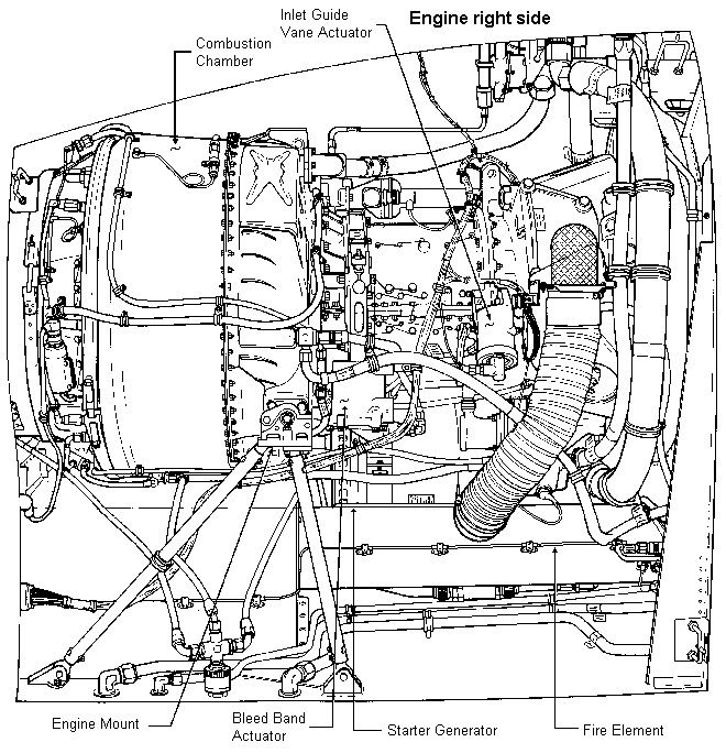
Combustion Section
The combustor section is constructed of welded titanium and steel and consists of an outer
housing and an inner liner which make up the reverse annular (ring-shaped) flow combustion
chamber. The outer housing is bolted to the diffuser section with 72 steel (heat
resistant) bolts. It also houses the combustor drain valve and has provisions for
attaching various fuel and oil lines and electrical wiring. The liner is of stamped and
welded construction and has 22 swirl cups into which the fuel nozzels extend. Fuel is
mixed with the compressed air at different points in the combustion chamber and burned.
The flame continually develops the hot gases which escape out across the n1 and
n2 turbines, turning them at a high rpm. The combustion liner contains louvers
and drilled passageways which control the incoming air for mixing with the fuel, cooling
and flame control. About two-thirds of the compressed air is used in flame control and
cooling and the remaining one-third for mixing with fuel for combustion.
Engine Mounts
The engine is rigidly mounted to the fuselage aft of the cabin on the work deck platform.
A free power turbine engine can be rigidly mounted because it lacks power stroke
vibrations and friction torque normally found in reciprocating engines. The engine mount
consist of a tripod attached to the left side of the diffuser section, a bipod attached to
the right side of the diffuser, and a support tube attached to the left side of the air
inlet section.
Interstage Air Bleed System (bleed band)
The interstage air bleed system is used to open and close air bleed holes located at the
aft end of the axial compressor housing thereby improving compressor acceleration
characteristics. The band is automatically open and closed by the actuator on a
differential of air pressure signal or a set rpm. The band is normally open below a set
rpm and during acceleration to prevent a back pressure buildup across the compressor rotor
blades. The back pressure, if allowed to develop, would decrease airflow velocity across
the airfoil shaped blades and cause them to stall, resulting in engine surges.
Starter Generator
The starter generator provides the turning force to start the engine and provides 28 VDC
power source.
Variable Inlet Guide Vane
The air inlet guide vanes are mounted between the inner and outer housings in the rear of
the air inlet section. They function to provide a surge (compressor stall) margin in the
engine. Engine surge is recognized as a loud popping and is caused by a stalling condition
across the airfoil surfaces of the compressor rotor blades or stator vanes. To prevent
this and to improve engine efficiency, the guide vanes control the angle of incidence of
the incoming air on the first stage of the axial compressor blades as the compressor rpm
varies. By this action the air's volume and velocity is controlled which prevents a
stalling condition to develop across the airfoil surfaces. At low N1 speeds,
the vanes are in the closed position. Opening of the vanes depends on ambient temperature
and N1 speed. The guide vanes are automatically opened and closed by fuel
pressure from the fuel control unit.
|
|
|
|
| Updated: 12 January 2008 |
|
Born on 13 October 1998 |