
|
|
|
|
|
The combustion section contains the combustion chambers, igniter plugs, and fuel nozzle or fuel injectors. It is designed to burn a fuel-air mixture and to deliver combusted gases to the turbine at a temperature not exceeding the allowable limit at the turbine inlet. Theoretically, the compressor delivers 100 percent of its air by volume to the combustion chamber. However, the fuel-air mixture has a ratio of l5 parts air to 1 part fuel by weight. Approximately 25 percent of this air is used to attain the desired fuel-air ratio. The remaining 75 percent is used to form an air blanket around the burning gases and to dilute the temperature, which may reach as high as 3500º F, by approximately one-half. This ensures that the turbine section will not be destroyed by excessive heat.
The air used for burning is known as primary air; that used for cording is secondary air. Secondary air is controlled and directed by holes and louvers in the combustion chamber liner. Igniter plugs function during starting only; they are shut off manually or automatically. Combustion is continuous and self-supporting. After engine shutdown or failure to start, a pressure-actuated valve automatically drains any remaining unburned fuel from the combustion chamber. The most common type used in Army gas turbine engines is the external annular reverse-flow type.
The primary function of the combustion section is, of course, to bum the fuel-air mixture, thereby adding heat energy to the air. To do this efficiently, the combustion chamber must —
The location of the combustion section is directly between the compressor and turbine sections. The combustion chambers are always arranged coaxially with the compressor and turbine, regardless of type, since the chambers must be in a through-flow position to function efficiently.
All combustion chambers contain the same basic elements:
There are currently three basic types of combustion chambers, varying in detail only:
The can-type combustion chamber is typical of the type used on both centrifugal and axial-flow engines (Figure 1). It is particularly well suited for the centrifugal compressor engine since the air leaving the compressor is already divided into equal portions as it leaves the diffuser vanes. It is then a simple matter to duct the air from the diffuser into the respective combustion chambers arranged radially around the axis of the engine. The number of chambers will vary; in the past as few as 2 and as many as 16 chamber's have been used. The present trend is about 8 or 10 combustion chambers. Figure 1 illustrates the arrangement of can-type combustion chambers. On American-built engines these chambers are numbered in a clockwise direction facing the rear of the engine with the No.1 chamber at the top.
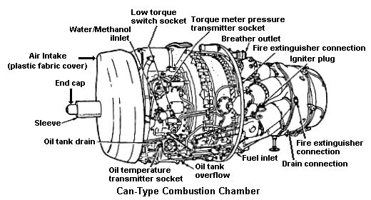
Figure 1
Each can-type combustion chamber consists of an outer case or housing with a perforated stainless steel (highly heat-resistant) combustion chamber liner or inner liner (Figure 2). The outer case is divided for ease of liner replacement. The larger section or chamber body encases the liner at the exit end; the Smaller chamber cover encases the front or inlet end of the liner.
Figure 2
The interconnector (flame propagation) tubes area necessary part of can-type combustion chambers. Since each can is a separate burner operating independently of the others, there must be some way to spread combustion during the initial starting operation. This is done by interconnecting all the chambers. The flame is started by the spark igniter plugs in two of the lower chambers; it passes through the tubes and ignites the combustible mixture in the adjacent chamber. This continues until all chambers are burning. The flame tubes will vary in construction details from one engine to another although the basic components are almost identical.
The interconnector tubes are shown in Figure 2. Bear in mind that not only must the chambers be interconnected by an outer tube (in this case, a ferrule), but there must also be a slightly longer tube inside the outer one to interconnect the chamber liners where the flame is located The outer tubes or jackets around the interconnecting flame tubes not only afford airflow between the chambers but also fulfill an insulating function around the hot flame tubes.
The spark igniters are normally two in number. They are located in two of the can-type combustion chambers.
Another very important requirement in the construction of combustion chambers is providing the means for draining unburned fuel. This drainage prevents gum deposits in the fuel manifold, nozzles, and combustion chambers. These deposits are caused by the residue left when fuel evaporates. If fuel is allowed to accumulate after shutdown there is the danger of after fire.
If the fuel is not drained, a great possibility exists that at the next starting attempt excess fuel in the combustion chamber will ignite and tailpipe temperature will go beyond safe operating limits.
The liners of can-type combustors have perforations of various sizes and shapes, each hole having a specific purpose and effect on flame propagation in the liner. Air entering the combustion chamber is divided by holes, louvers, and slots into two main streams — primary and secondary air. Primary (combustion) air is directed inside the liner at the front end where it mixes with the fuel and bums. Secondary (cooling) air passes between the outer casing and the liner and joins the combustion gases through larger holes toward the rear of the liner, cooling the combustion gases from about 3500º F to near 1500º F.
Holes around the fuel nozzle in the dome or inlet end of the can-type combustor liner aid in atomization of the fuel. Louvers are also provided along the axial length of the liners to direct a cooling layer of air along the inside wall of the liner. This layer of air also tends to control the flame pattern by keeping it centered in the liner, preventing burning of the liner walls.
Figure 3 illustrates the flow of air through the louvers in the double-annular combustion chamber.
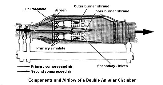
Figure 3
Some provision is always made in the combustion chamber case or in the compressor air outlet elbow for installation of a fuel nozzle. The fuel nozzle delivers the fuel into the liner in a freely atomized spray. The freer the spray, the more rapid and efficient the burning process. Two types of fuel nozzles currently being used in the various types of combustion chambers are the simplex nozzle and the duplex nozzle.
The annular combustion chamber consists basically of a housing and a liner, as does the can type. The liner consists of an undivided circular shroud extending all the way around the outside of the turbine shaft housing. The chamber may be constructed of one or more baskets. If two or more chambers are used, one is placed outside the other in the same radial plane; hence, the term "double-annular chamber."
The spark igniter plugs of the annular combustion chamber are the same basic type used in the can combustion chambers, although construction details may vary. There are usually two plugs mounted on the boss provided on each of the chamber housings. The plugs must be long enough to protrude from the housing into the outer annulus of the double-annular combustion chamber.
The annular-type combustion chamber is used in many engines designed to use the axial-flow compressor. It is also-used by engines incorporating dual-type compressors (combinations of axial flow and centrifugal flow). Its use permits building an engine of small diameter. Instead of individual combustion chambers, the compressed air is introduced into an annular space formed by a combustion chamber liner around the turbine shaft. Usually, enough space is left between the outer liner wall and the combustion chamber housing to permit the flow of cooling air from the compressor. Fuel is introduced through nozzles or injectors connected to a fuel manifold. The nozzle opening may face upstream or downstream to airflow depending on engine design. Various means are provided to introduce primary (compressed) air to the vicinity of the nozzle or injectors to support combustion and additional air downstream to increase the mass flow. Secondary cooling air reduces the temperature of gases entering the turbine to the proper level,
Some axial compressor engines have a single annular combustion chamber similar to that shown in Figure 4. The liner of this type of burner consists of continuous, circular, inner and outer shrouds around the outside of the compressor drive shaft housing. Holes in the shrouds allow secondary cooling air to enter the center of the combustion chamber. Fuel is introduced through a series of nozzles at the upstream end of the liner. Because of their proximity to the flames all types of burner liners are short-lived in comparison to other engine components; they require more frequent inspection and replacement.
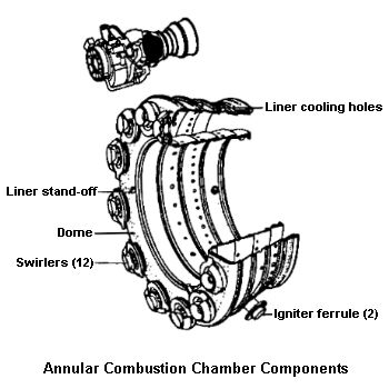
Figure 4
This type of burner uses the limited space available most effectively, permitting better mixing of the fuel and air within a relatively simple structure. An optimum ratio of burner inner surface area to volume is provided; this ensures maximum cooling of the gases as combustion occurs. The design also tends to prevent heat warping However, the burner liner on some engines cannot be disassembled without removing the engine from the aircraft — a distinct disadvantage.
The latest annular combustion system for military use is a low-pressure fuel injection system with vortex air swirlers to mix fuel and compressor discharge air before combustion. The fuel injector is positioned into the center of an air swirler in the dome of the liner. Fuel leaving the injectors (which has been swirled) is surrounded by a concentric air vortex pattern. This breaks fuel particles down to an extremely small size before they reach the combustion zone, This creates excellent fuel-air mixing that ensures a low smoke level in the exhaust. The low-pressure fuel system does not have tine nozzle orifices and can handle contaminated fuel without clogging.
The can-annular-type combustion chamber was developed by Pratt and Whitney for use in their JT3 axial-flow turbojet engine. Since this engine features the split-spool compressor, it needed a combustion chamber capable of meeting the stringent requirements of maximum strength and limited length plus high overall efficiency. These were necessary because of the high air pressures and velocities in a split-spool compressor along with the shaft length limitations explained below.
The split compressor requires two concentric shafts to join the turbine stages to their respective compressors. The front compressor joined to the rear turbine stages requires the longer shaft. Because this shaft is inside the other, a limitation is imposed on diameter. The distance between the front compressor and the rear turbine must be limited if critical shaft lengths are to be avoided.
Since the compressor and turbine are not susceptible to appreciable shortening the necessary shaft length limitation had to be absorbed by developing a new type of burner. A design was needed that would give the desired performance in much less relative distance than had previously been assigned.
Can-annular combustion chambers are arranged radially around the axis of the engine in this instance the rotor shaft housing. The combustion chambers are enclosed in a removable steel shroud that covers the entire burner section. This feature makes the burners readily available for any required maintenance.
The burners are interconnected by projecting flame tubes. These tubes make the engine-starting process easier. They function identically with those previously discussed but differ in construction details.
Each combustion chamber contains a central bullet-shaped perforated liner. The size and shape of the holes are designed to admit the correct quantity of air at the correct velocity and angle. Cutouts are provided in two of the bottom chambers for installation of the spark igniters. The combustion chambers are supported at the aft end by outlet duct clamps. These clamps secure them to the turbine nozzle assembly.
The forward face of each chamber presents six apertures which align with the six fuel nozzles of the corresponding fuel nozzle duster. These nozzles are the dual-orifice (duplex) type. They require a flow divider (pressurizing valve) as was mentioned above in the can type combustion chamber discussion. Around each nozzle are preswirl vanes for imparting a swirling motion to the fuel spray. This results in better atomization burning and efficiency.
Swirl vanes perform two important functions. They cause —
Swirl vanes greatly aid flame propagation because a high degree of turbulence in the early combustion and cooling stage is desirable. Vigorous mechanical mixing of fuel vapor with primary air is necessary; mixing by diffusion alone is too slow. Mechanical mixing is also done by other measure; for example, placing coarse screens in the diffuser outlet as is done in most axial-flow engines.
Can-annular combustion chambers must also have fuel drain valves in two or more of the bottom chambers. This ensures drainage of residual fuel to prevent its being burned at the next start.
The flow of air through the holes and louvers of the can-annular chambers is almost identical with the flow through other types of burners. Special baffling is used to swirl the combustion airflow and to give it turbulence.
Performance requirements include —
All of the burner requirements must be satisfied over a wide range of operating conditions. For example, airflows may vary as much as 50:1, fuel flows as much as 30:1, and fuel-air ratios as much as 5:1. Burner pressures may cover a ratio of 100:1, while burner inlet temperatures may vary by more than 700º F.
The effect of operating variables on burner performance is —
|
|
|
|
| Updated: 12 January 2008 |
|
Born on 08 March 1999 |