
|
|
|
|
|
The compressor section of the turbine engine has many functions. Its primary function is to supply enough air to satisfy the requirements of the combustion burners. The compressor must increase the pressure of the mass of air received from the air inlet duct and then discharge it to the burners in the required quantity and pressure.
A secondary function of the compressor is to supply bleed air for various purposes in the engine and aircraft. The bleed air is taken from any of the various pressure stages of the compressor. The exact location of the bleed port depends on the pressure or temperature required for a particular job. The ports are small openings in the compressor case adjacent to the particular stage from which the air is to be bled. Varying degrees of pressure and heat are available simply by tapping into the appropriate stage. Air is often bled from the final or highest pressure stage because at this point pressure and air temperature are at a maximum. At times it may be necessary to cool this high-pressure air. If it is used for cabin pressurization or other purposes where excess heat would be uncomfortable or detrimental the air is sent through a refrigeration unit.
Bleed air has various uses including driving the remote-driven accessories. Some current applications of bleed air are —
Compressor section location depends on the type of compressor. In the centrifugal-flow engine the compressor is between the accessory section and the combustion section; in the axial-flow engine the compressor is between the air inlet duct and the combustion section.
The centrifugal-flow compressor basically consists of an impeller (rotor), a diffuser (stator), and a compressor manifold. The impeller and the diffuser are the two main functional elements. Although the diffuser is a separate component positioned inside and secured to the manifold, the entire assembly (diffuser and manifold) is often referred to as the diffuser.
The impeller's function is to pick up and accelerate air outward to the diffuser. Impellers may be either of two types — single entry or double entry. Both are similar in construction to the reciprocating engine supercharger impeller. The double-entry type is similar to two back-to- back impellers. However, because of much greater combustion air requirements in turbine engines, these impellers are larger than supercharger impellers.
The principal differences between the two types of impellers are size and ducting arrangement. The double-entry type has a smaller diameter but is usually operated at a higher rotational speed to ensure enough airflow. The single-entry impeller permits convenient ducting directly to the impeller eye (inducer vanes) as opposed to the more complicated ducting necessary to reach the rear side of the double-entry type. Although slightly more efficient in receiving air, the single-entry impeller must be large in diameter to deliver the same quantity of air as the double-entry type. This of course, increases the overall diameter of the engine.
Included in the ducting for double-entry compressor engines is the plenum chamber. This chamber is necessary for a double-entry compressor because air must enter the engine at almost right angles to the engine axis. To give a positive flow, air must surround the engine compressor at a positive pressure before entering the compressor.
Multistage centrifugal compressors consist of two or more single compressors mounted in tandem on the same shaft. The air compressed in the first stage passes to the second stage at its point of entry near the hub. This stage will further compress the air and pass it to the next stage if there is one. The problem with this type of compression is in turning the air as it is passed from one stage to the next.
The diffuser is an annular chamber provide with a number of vanes forming a series of divergent passages into the manifold. The diffuser vanes direct the flow of air from the impeller to the manifold at an angle designed to retain the maximum amount of energy imparted by the impeller. They also deliver the air to the manifold at a velocity and pressure satisfactory for combustion chambers.
The compressor manifold diverts the flow of air from the which, which is an integral part of the manifold, into the combustion chambers. The manifold will have one outlet port for each chamber so that the air is evenly divided. A compressor outlet elbow is bolted to each of the outlet ports. These air outlets are constructed in the form of ducts and are known by a variety of names including "air outlet ducts", "outlet elbows," and "combustion chamber inlet ducts." These outlet ducts perform a very important part of the diffusion process. They change the airflow direction from radial to axial. The diffusion process is completed after the turn. To help the elbows perform this function efficiently, turning vanes (cascade vanes) are sometimes fitted inside the elbows. The vanes reduce air pressure losses by presenting a smooth, turning surface.
The centrifugal compressor is used best on smaller engines where simplicity, flexibility, and ruggedness are primary requirements. These have a small frontal area and can handle high airflows and pressures with low loss of efficiency.
Centrifugal-flow compressors have the following advantages:
They have the following disadvantages:
Axial-flow compressors have two main elements: a rotor (drum or disc type) and a stator. These compressors are constructed of several different materials depending on the load and operating temperature. The drum-type rotor consists of rings that are flanged to fit one against the other so that the entire assembly can be held together by through bolts. This type of construction is satisfactory for low-speed compressors where centrifugal stresses are low (Figure-1). The rotor (disc-type) assembly consists of —
Figure 1
Rotor blades are generally machined from stainless steel forgings, although some may be made of titanium in the forward (colder) section of the compressor (Figure 2). The blades are attached in the disc rim by different methods using either the fir-tree-type, dovetail-type, or bulb-type root designs. The blades are then locked into place with screws, peening, locking wires, pins, keys, or plates (Figure 3). The blades do not have to fit too tightly in the disc because centrifugal force during engine operation causes them to seat. Allowing the blades some movement reduces the vibrational stresses produced by high-velocity airstreams between the blades. The newest advance in technology is a one-piece design machined blade disc (combined disc and blade); both disc and rotor blade are forged and then machined into one (refer to Figure 2 again).
Figure 2
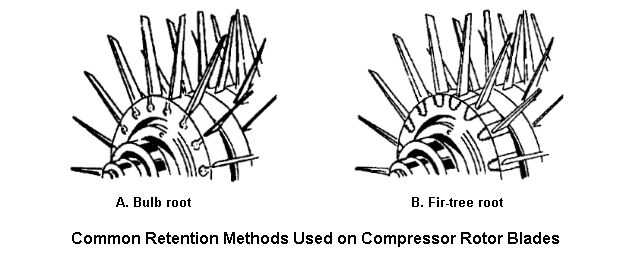
Figure 3
Clearances between rotor blades and the outer case are very important to maintain high efficiency. Because of this, some manufacturers use a "wear fit" design between the blade and outer case. Some companies design blades with knife-edge tips that wear away to form their own clearances as they expand from the heat generated by air compression. Other companies coat the inner surface of the compressor case with a soft material (Teflon) that can be worn away without damaging the blade. Rotor discs that are joined together by tie bolts use serration splines or curve coupling teeth to prevent the discs from turning in relation to each other. Another method of joining rotor discs is at their rims.
Axial-flow compressor casings not only support stator vanes and provide the outer wall of the axial paths the air follows but also provide the means for extracting compressor air for various purposes. The stator and compressor cases show great differences in design and construction. Some compressor cases have variable stator vanes as an additional feature. Others (compressor cases) have fixed stators. Stator vanes may be either solid or hollow and mayor may not be connected at their tips by a shroud. The shroud serves two purposes. First, it provides support for the longer stator vanes located in the forward stages of the compressor second, it provides the absolutely necessary air seal between rotating and stationary parts. Some manufacturers use split compressor cases while others favor a weldment, which forms a continuous case. The advantage of the split case is that the compressor and stator blades are readily available for inspection or maintenance. On the other hand the continuous case offers simplicity and strength since it requires no vertical or horizontal parting surface.
Both the case and the rotor are very highly stressed parts. Since the compressor turns at very high speeds the discs must be able to withstand very high centrifugal forces. In addition the blades must resist bending loads and high temperatures. When the compressor is constructed each stage is balanced as a unit. The compressor case in most instances is one of the principal structural, load-bearing members of the engine. It may be constructed of aluminum steel, or magnesium.
Axial-flow compressors have the following advantages:
They have the following disadvantages:
The air in an axial compressor flows in an axial direction through a series of rotating (rotor) blades and stationary (stator) vanes that are concentric with the axis of rotation. Unlike a turbine, which also employs rotor blades and stator vanes the flow path of an axial compressor decreases in cross-sectional area in the direction of flow. This reduces the volume of air as compression progresses from stage to stage.
After being delivered to the face of the compressor by the air inlet duct incoming air passes through the inlet guide vanes. Upon entering the first set of rotating blades, the air, which is flowing in a general axial direction is deflected in the direction of rotation. The air is arrested and turned as it is passed on to a set of stator vanes. Following that it is picked up by another set of rotating blades and soon through the compressor. Air pressure increases each time it passes through a set of rotors and stators.
The rotor blades increase the air velocity. When air velocity increases, the ram pressure of air passing through a rotor stage also increases. This increase in velocity and pressure is somewhat but not entirely nullified by diffusion. When air is forced past the thick sections of the rotor blades static pressure also increases. The larger area at the rear of the blades (due to its airfoil shape) acts as a diffuser.
In the stators velocity decreases while static pressure increases. As air velocity decreases, the pressure due to velocity or ram that has just been gained in Passing through preceding rotor stage decreases somewhat; however, the total pressure is the sum of static pressure and pressure due to ram. Successive increases and decreases in velocity as air leaves the compressor are usually only slightly greater than the velocity of the air at the entrance to the compressor. As the pressure is built up by successive sets of rotors and stators, less and less volume is required. Thus, the volume within the compressor is gradually decreased. At the exit of the compressor, a diffuser section adds the final stage to the compression process by again decreasing velocity and increasing static pressure just before the air enters the engine burner section.
Normally, the temperature change caused by diffusion is not significant by itself. The temperature rise which causes air to get hotter and hotter as it continues through the compressor, is the result of the work being done on the air by the compressor rotors. Heating of the air occurs because of the compression process and because some of the mechanical energy of the rotor is converted to heat energy.
Because airflow in an axial compressor is generally diffusing it is very unstable. High efficiency is maintained only at very small rates of diffusion. Compared to a turbine, quite a number of compressor stages are needed to keep the diffusion rate small through each individual stage. Also, the permissible turning angles of the blades are considerably smaller than those which can be used in turbines. These are the reasons why an axial compressor must have many more stages than the turbine which drives it. In addition, more blades and consequently more stages are needed because the compressor, in contrast to a turbine, is endeavoring to push air in a direction that it does not want to go in.
The dual compressor is a combination either of two axial compressors or of an axial and a centrifugal compressor (Figure 4). The dual-axial compressor consists of a low-pressure compressor in front and a high-pressure compressor in the rear. Both compressors (low and high) are driven by two different shafts that connect to different turbines. The starter is usually connected to the high-pressure compressor because it reduces the torque required to start the engine. With the rear (high-pressure) compressor turning at governed Speed, the front (low-pressure) compressor (not governed) is automatically rotated by its turbine. Rotation speed is whatever speed will ensure an optimum flow of air through the compressor. With the front and rear compressor rotors working in harmony instead of interfering with each other, compression rates can be increased without decreasing efficiency. Due to the added length of the engine this type of compressor is found on turbojet aircraft.
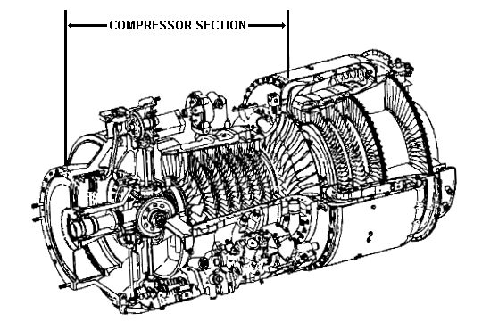
Figure 4
Most gas turbines in Army aircraft have a combination of an axial compressor (front) and a centrifugal compressor (rear). The usual combination is a five-or seven-stage axial-flow compressor and a centrifugal-flow compressor. The axial compressor and centrifugal compressor combination is mounted on the same shaft; the compressors turn in the same direction and at the same speed. By combining them, the manufacturer makes the most of the advantages of both compressors small frontal area, increased compression ratios, and shortened overall engine length. Using the centrifugal-flow compressor boosts compression and increases efficiency of the turbine engine. The centrifugal compressor also shortens the length of the engine. If the centrifugal compressor were not added, the manufacturer would have to add more stages of axial compression to equal that of the centrifugal compressor.
_ _ _ _ _ _ _ _ _ _
Compressors Directory|
|
|
|
| Updated: 12 January 2008 |
|
Born on 06 March 1999 |