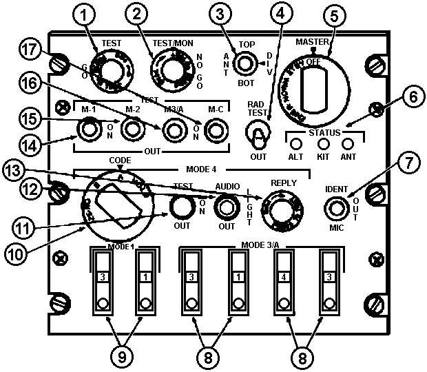
| CONTROL/INDICATOR |
FUNCTION |
| 1. TEST GO |
Indicates successful built in test (BIT) |
| 2. TEST/MON NO GO |
Illuminates to indicate unit malfunction. |
| 3. ANT |
|
TOP
|
Selects antenna located on top of helicopter. |
BOT
|
Selects antenna located on bottom of helicopter. |
DIV
|
Monitor received signals from both antennas and allows transmission via
antenna receiving the strongest signal. |
| 4. RAD TEST switch |
|
RAD TEST
|
Enables set to reply to TEST mode interrogations. |
OUT
|
Disables to RAD TEST features. |
| 5. MASTER control |
|
OFF
|
Turns set off |
STYB
|
Places in warm-up (standby) condition. |
NORM
|
Set operates at normal receiver sensitivity. |
EMER
|
Transmits emergency replay signal to MODE 1, 2, or 3/A interrogations
regardless of mode control settings. |
| 6. STATUS indicators |
|
ANT
|
Indicates that built in test (BIT) or monitor (MON) failure is due to
high-voltage standing wave ratio (VSWR) in antenna. |
KIT
|
Indicates that built in test (BIT) or monitor (MON) failure is due to
external computer. |
ALT
|
Indicates that built in test (BIT) or monitor (MON) failure is due to
altitude digitizer. |
| 7. IDENT-MIC switch |
|
IDENT
|
Indicates identification reply for approximately 25 seconds. |
OUT
|
Prevents triggering of identification reply. Spring loaded to OUT. |
MIC
|
Not used. |
| 8. MODE 3/A code select switches |
Selects and indicates the MODE 3/A four-digit reply code number. |
| 9. MODE 1 code select switches |
Selects and indicates the MODE 1 two-digit reply code number. |
10. MODE $/CODE control
HOLD/A/B/ZERO |
Selects condition of code changer in remote computer. |
| 11. MODE 4 TEST switch |
|
TEST
|
Selects MODE 4 BIT operation. |
ON
|
Selects MODE 4 ON operation. |
OUT
|
Disables MODE 4 operation. |
| 12. MODE $ AUDIO/LIGHT control |
|
AUDIO
|
MODE 4 is monitor by audio. |
LIGHT
|
MODE 4 is monitor by light. |
OUT
|
MODE 4 not monitored. |
| 13. MODE 4/REPLY |
Indicates that a MODE 4 reply is generated. |
| 14. TEST/M-1 |
|
TEST/ON/OUT
|
Selects ON, OFF or BIT of MODE 1 operation. |
| 15. TEST/M-2 |
|
TEST/ON/OUT
|
Selects ON, OFF or BIT of MODE 2 operation. |
| 16. TEST/M-3/A |
|
TEST/ON/OUT
|
Selects ON, OFF or BIT of MODE 3/A operation. |
| 17. TEST/M-C |
|
TEST/ON/OUT
|
Selects ON, OFF or BIT of MODE C operation. |


