| Item |
Function |
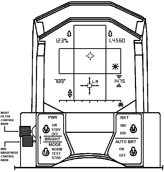
| PWR Switch |
|
| ON |
Electrical power applied, symbols displayed depend on MODE
switch position. |
| STBY |
Electrical power applied, no symbols displayed. |
| OFF |
All electrical power removed from HUD circuits. |
| MODE Switch |
|
| NORM |
All basic symbols displayed. |
| TEST |
Displays all heads up display symbols. |
| STAD |
Displays stadiametric reticle which is a backup reticle. |
| RKT Switch |
|
| IND |
Displays a continually computed rocket release point. |
| DIR |
Displays a continuously computed rocket impact point. |
| AUTO BRT Switch |
|
| ON |
Allows brightness of displayed symbols to be automatically
adjusted. |
| OFF |
Disables automatic brightness control feature. |
| NIGHT FILTER Control Knob |
Selects usage of night filter by rotating knob. |
HUD BRIGHTNESS
Control Knob |
Controls brightness of heads up display element when rotated
as shown by BRIGHT arrow. |
| Symbol |
Description |
|
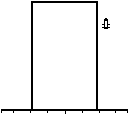
TOW Prelaunch. Displayed in prelaunch mode only. Either left
or right missile is displayed dependent upon missile selected. Vertical positioned
rectangle is switched to horizontal position when fire control status has changed from TOW
attack to TOW fire. Scale factor of area covered by rectangle to real world is 1:1 in
azimuth and elevation.
|

|
TOW Postlaunch. Fixed horizontal rectangle displayed 1.5
seconds after TOW missile is fired. Scale factor of area covered by rectangle to real
world is 23:1 in azimuth and elevation. TOW postlaunch window is removed from HUD display
at wire cut.
|

|
Ascend. Displayed in lower left corner. Arrowhead pointing
vertically up is a command, indicating nose of aircraft must be raised before firing TOW
missile. Symbol extinguishes when required attitude is reached. |

|
Descend. Displayed in lower left corner. Arrowhead pointing
vertically down is a command indicating nose of aircraft must be lowered before firing TOW
missile. Symbol extinguishes when required attitude is reached. |

|
Engine torque. Displayed in upper left corner. Display
indicates percent of rated torque. One to three digit number followed by percent sign.
Display ranges from 0 to 145.
Range. Displayed in upper right corner. 1 to 4 digit
number. L indicates raw laser range input information.
F indicates Fire Control Computer input information.
Number changes in 10 meter increments; i.e., last number is always zero.
Display ranges from 10 meters to 9.99km.
|

|
Magnetic Heading. Heading of aircraft with respect to
magnetic north. Displayed in lower left corner of HUD. Three digit number followed by
degree sign. Display indicates from 0 to 359.
Altitude. Displayed in lower right corner, one to four digit number indicates in feet, in
increments of 5 feet. Display is blanked above 1499 feet and reappears at 1475 feet.
|

|
Upper/Lower Radar Altitude. Arrowheads pointing at altitude
numerics from above and below. Arrowheads appear when preset upper or lower altitude
limits are reached. Input information from radar altimeter. |

|
Boresight Reference Symbol. Stationary and centered on ADL.
Displayed in all modes except stadiametric mode. |

|
Gunner's LOS cueing. Cross hairs, location of symbol on
display indicates position TSU is pointing (looking) at. In normal modes, if gunner is
looking outside the HUD field of view (FOV) limits, the LOS CUE symbol will be limited at
edge of FOV and be overlayed by an
X. In TOW mode, under these conditions, the
X will flash at a 4 Hz rate. |

|
Caution Symbol. When fire control reticle gunner's LOS cueing
and/or coarse azimuth pointer symbol reach or exceed outer display limits, a Caution
symbol superimposes each out-of-limit symbol. In TOW mode, the
X will flash at 4 Hz rate whenever the TOW firing constraints
are not met. Caution extinguishes when symbols are within limits.
|

|
Azimuth (AZ) course scale and AZ course pointer. Pointer
represents position of Telescopic Sight Unit (TSU) with respect to aircraft datum line
(ADL). Displayed in all modes except STAD mode. Scale divisions are ±30°, ±60°,
±90°, ±110° measured from 0° scale center. Caution symbol superimposes pointer when
it reaches ±110°. Scale is stationary, pointer moves in horizontal plane only.
|
|
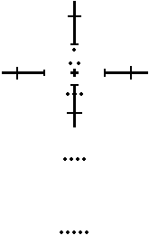
Stadiametric Reticle. Fixed Aiming Reticle for Rocket Fire.
Used in event both the FCC and Laser have failed. This symbol is generated entirely within
the HUD. Pilot will estimate range to target, and line up target with appropriate range
marker on Stadiametric Reticle. (Each dot represents 1000 meters) Example: If estimated
target range is 2000 meters, align aircraft such that the 2 dots just above center cross
hairs overlay target. The positioning of dots are based on the ballistics equation for
rockets. The tick marks are for additional range/angle reference, and are spaced specific
number of mils apart.
|
|
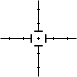
Direct Rocket Reticle. Used in Direct Rocket Mode. Reticle
position on display is the Continuously Computed Impact Point (CCIP) of the weapon if the
pilot were to fire at that instant. Moves in both X and Y direction. Tick marks are for
range/angle estimation, in MIL spacing. Caution symbol is superimposed across reticle
center when reticle reaches display FOV limits |
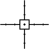
|
Fixed Gun Reticle. Used when firing fixed guns from wing
pods. Reticle is in fixed position centered on the Armament Datum Line (ADL). |
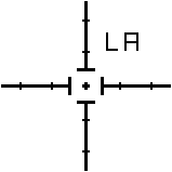
|
Backup Direct Rocket Reticle. Used when Fire Control Computer
(FCC) has failed. Positioned in elevation only as a function of raw laser range (LA). |
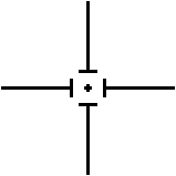
|
Indirect Rocket Reticle. Displayed in Indirect Rocket mode
only. Movable in X and Y direction. Represents a Continuously computed Release Point
(CCRP), which is the point in space from which to launch weapon to hit target. Caution
symbol is superimposed across reticle center when reticle reaches display FOV limits. |


