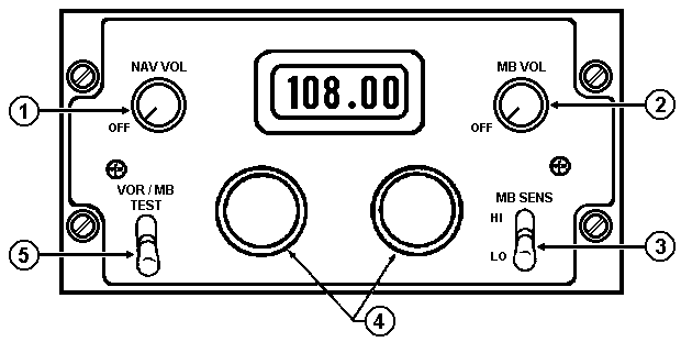
VOR / LOC / GS / MB Control Panel

C-10048/ARN-123
| Control / Indicator |
Function |
| 1. NAV VOL power switch and volume control |
|
|
NAV VOL
|
Turns set on and controls receiver volume. |
|
OFF |
Turns set OFF. |
|
|
| 2. MB VOL power switch and volume control |
|
|
MB VOL |
Turns set on and controls volume. |
|
OFF |
Turns set OFF |
|
|
| 3. MB SENS switch |
|
|
HI |
Increases MB lamp brilliance and audible output
as required. |
|
LO |
Decreases MB lamp brilliance and audible output
as required. |
|
|
| 4. Frequency selectors |
|
|
Right |
Selects the fractional megahertz portion of the
desired frequency. |
|
Left |
Selects the whole megahertz portion of the
desired frequency. |
|
|
| 5. VOR / MB TEST switch |
Provides on and off capability for the VOR / MB
self-test circuits within the receiver. |
VOR / LOC / GS / MB System
The VOR / LOC / GS / MB Radio Receiving Set AN/ AN-123(V)1 receives the
combined VOR (VHF omni-range) and LOC (localizer) signals over a frequency range
of 108.00 to 117.95 MHz, GS (glideslope) signals over a frequency range of
329.15 to 335.00 MHz, and MB (marker beacon) signals on 75.00 MHz from ground
transmitters. The signals drive the pilot
HSI and ADI
as applicable, the gunner (RMI) radio bearing pointers, and the marker beacon
lights as required. Audio signals may also be received, from the ground
transmitters, through the helicopter's intercommunications system by placing the
interphone control AUX switch in ON. The set enables the operator to determine
his present position, direction to a given point, and fly a predetermined
flight-path to desired destination relative to a VOR facility. The localizer
circuitry provides a visual display and aural tone to indicate helicopter
position relative to a marker beacon transmitter.
| Updated:
12 January 2008
|
|
Born on 06 September 1999 |


