
|
|
|
|
|
In their early attempts at flight human kind soon learned that the human body was totally inadequate as a propulsion device. They also learned that heavier-than-air aircraft would need power to attain and sustain flight. Early efforts to develop a satisfactory engine included rocket, steam, jet, and reciprocating engines, but it was the reciprocating engine that first pushed the Wright brothers aloft. Today's Army aircraft are propelled by gas turbine and reciprocating engines. While the technology which led to these engines is relatively new, the idea is not.
Hero, an Egyptian scientist from Alexandria, developed the first "jet engine" about the year 100 BC. Known as the "aeolipile" (Figure 1), it consisted of a boiler, two hollow bent tubes mounted to a sphere, and the sphere. Steam coming from the boiler entered through the two hollow tubes supporting the sphere. The steam then exited through the bent tubes on the sphere, causing it to spin. Hero is said to have used this invention to pull-open temple doors.
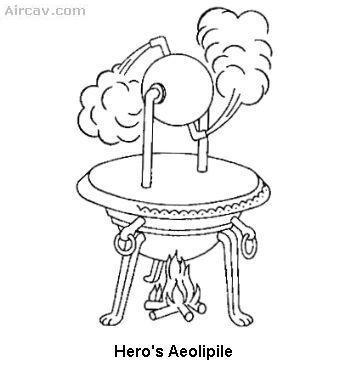
Figure 1
Leonardo Da Vinci designed a device called the "chimney jack" around the year 1500 AD. The chimney jack was used to turn a roasting skewer. This reaction-type turbine worked on the principle of heat raising gases from the roasting tire. As the hot air rose, it passed through fanlike blades that turned the roast through a series of gears.
With the discovery of gunpowder around 1000 AD the Chinese, probably accidentally through a defective firecracker developed the rocket. Rockets were used as early as 1232 by the Mongols to create fear among enemy troops. A Chinese scholar, Wan Hu attempted to propel his sled with rockets. He became the first martyr in humankind's attempts to fly. Rockets were used in the Napoleonic Wars and the War of 1812. The Germans used V-2 rockets in World War II The most noted use of rockets is to launch space vehicles.
In 1629 an Italian engineer, Giovanni Branca, was probably the first to invent an actual impulse turbine. This device, a stamping mill (Figure 2), was generated by a steam-powered turbine. A jet nozzle directed steam onto a horizontally mounted turbine wheel, which then turned an arrangement of gears that operated his mill.
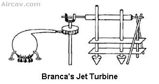
Figure 2
In 1687 Isaac Newton attempted to put his newly formulated laws of motion to the test with his "steam wagon" (Figure 3). He tried to propel the wagon by directing steam through a nozzle pointed rearward Steam was produced by a boiler mounted on the wagon. Due to lack of power from the steam, this vehicle didn't operate.

Figure 3
In 1791 John Barber, an Englishman. was the first to patent a design that used the thermodynamic cycle of the modem gas turbine. His design (Figure 4) contained the basics of the modem gas turbine it had a compressor, a combustion chamber, and a turbine. The main difference in his design was that the turbine was equipped with a chain-driven reciprocating type of compressor. He intended its use for jet propulsion.
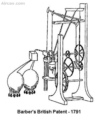
Figure 4
In January 1930 an Englishman, Frank Whittle, submitted a patent application for a gas turbine for jet propulsion. It wasn't until the summer of 1939 that the Air Ministry awarded Power Jets Ltd a contract to design a flight engine. In May 1941 the Whittle W1 engine (Figure 5) made its first flight mounted in the Gloster Model E28/39 aircraft. This airplane would later achieve a speed of 370 MPH in level flight with 1000 pounds of thrust.

Figure 5
The Germans, Hans von Ohain and Max Hahn, students at Gottingen, seemingly unaware of Whittle's work patented a jet propulsion engine in 1936. Ernst Heinkel Aircraft Company adapted their ideas and flew the second aircraft engine of this development in an HE-178 aircraft (Figure 6) on August 27, 1939. This was the first true jet-propelled aircraft. The engine, known as the Heinkel HES-36, developed 1100 pounds of thrust and hurled the HE-178 to speeds of over 400 MPH. This engine used a centrifugal flow compressor. Later development produced a more advanced turbine engine that used an axial flow compressor. This turbine was used to power the ME262 jet fighter to 500 MPH. These planes were introduced in the closing stages of World War II. The more modern engine features of blade cooling, ice prevention, and the variable-area exhaust nozzle were incorporated into the ME262 aircraft engine. On September 30, 1929, using a modified glider and Opel rockets, the Germans were the first to achieve flight using a reaction engine.
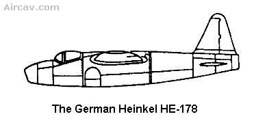
Figure 6
An Italian, Secundo Campiri of the Caproni Company, developed a turbine engine that used a 900-HP reciprocating engine to drive its three-stage compressor. This turbine was installed in the Caproni-Campiri CC-2, but it only achieved a disappointing 205 MPH. In August 1940 the CC-2 made its first flight, with the whole project ending just eight years later.
With the help of the British, America entered the jet propulsion field in September 1941. The W. lX engine, a complete set of plans for the W.2B engine, and a group of Power Jets engineers were flown to the United States from Britain. A contract was awarded General Electric Corporation to develop an American version of The W.IX. One year later (October 1942) the Bell XP-59A (Figure 7), fitted with two General Electric l-A engines (rated at 1300 pounds of thrust each) made this country's first jet propulsion flight.

Figure 7
Although General Electric introduced America to jet propulsion with its modified Whittle design, Westinghouse Corporation gave America its own gas turbine engine. The Westinghouse engine included an axial compressor and an annular combustion chamber. These two Westinghouse designs (axial compressor and annular combustion chamber) or variations thereof are still being used in turbine engines.
Newton's first law states a body in a state of rest remains at rest; a body in motion tends to remain in motion at a constant speed and in a straight line unless acted upon by some external force.
The first part of this law is evident from everyday experience for instance, a book placed on a table stays on the table. The second part of the law is more difficult to visualize. It states that if a body is set in motion and left to itself, it virtually keeps on moving without the action of any further force. The statement is correct; the body would continue to move without any reduction in velocity if no force acted upon it. However, experience shows that a retarding force (friction) is always present. A block of wood thrown to slide along a cement-paved road comes to rest after sliding only a short distance because the friction is great; along a waxed floor it would slide farther because the friction is less, along a sheet of ice it would slide much farther because the fiction is much less. From examples like these it is theorized that if friction were eliminated entirely, a body once set in motion on a level surface would continue to move indefinitely with undiminished velocity.
Newton's second law states: an unbalance of forces on a body produces or tends to produce an acceleration in the direction of the greater force; the acceleration is directly proportional to the force and inversely proportional to the mass of the body.
The meaning of the second law is illustrated by the example of two identical boxes being moved across a floor. If more force is applied to one box than to the other, the one subjected to the greater force will have greater acceleration. Or if a full box and an empty one are drawn across the floor with exactly equal forces, the empty box has the greater acceleration. In general, the greater the unbalanced force and the smaller the mass, the greater the acceleration.
Newton's third law states: for every action there is an equal and opposite reaction; the two actions are directed along the same straight line. In this statement the term "action" means the force that one body exerts on a second, and "reaction" means the force that the second body exerts on the first. That is, if body A exerts a force on body B, then B must exert an equal and opposite force on A. Note that action and reaction, though equal in magnitude and opposite in direction, never neutralize or cancel each other for they always act on different objects.
The recoil of a rifle demonstrates this law of action-reaction. The gunpowder in a charge is ignited by the ignition cap, combustion takes place, and the bullet is rapidly accelerated from the rifle. As a result of this action, the rifle is accelerated rearward against the shoulder of the person firing it. The recoil felt by the person is the reaction to the action which ejected the bullet.
The principle of jet propulsion can be illustrated by a toy balloon (Figure 8). When inflated with the stem sealed, pressure is exerted equally on all internal surfaces.
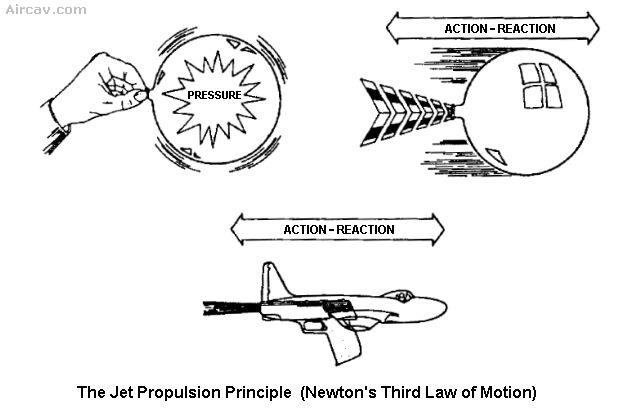
Figure 8
Since the force of this internal pressure is balanced, there is no tendency for the balloon to move. If the stem is released, the balloon will move in a direction away from the escaping jet of air. Although the flight of the balloon may appear erratic, it is moving in a direction away from the open stem at all times.
The balloon moves because of an unbalanced condition existing in it. The jet of air does not have to push against the outside atmosphere it could function better in a vacuum. When the stem area of the balloon is released, a convergent nozzle is created. As the airflows through this area, velocity is increased accompanied by a decrease in air pressure. In addition, an area of the balloon's skin against which the internal forces had been pushing removed. On the opposite internal surface of the balloon, an equal area of skin still remains. The higher internal pressure acting on this area moves the balloon in a direction away from the open stem. The flight of the balloon will be of short duration, though, due to the amount of air contained within it. If a source of pressurized air were provided, it would be possible to sustain the balloon's flight.
The "Brayton cycle" (Figure 9) is the name given to the thermodynamic cycle of a gas turbine engine to produce thrust. This is a varying-volume, constant-pressure cycle of events and is commonly called the "constant-pressure cycle" or "open cycle." A more recent term is "continuous-combustion cycle."
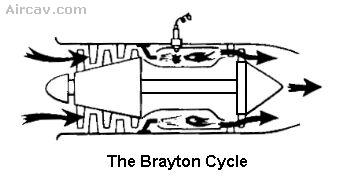
Figure 9
The four continuous and constant events are: intake, compression, expansion (includes power), and exhaust. These cycles will be discussed as they apply to a gas turbine engine.
In the intake cycle air enters at ambient pressure and in a constant volume and leaves at an increased pressure and decreased volume. In the compressor section air is received from the intake at increased pressure slightly above ambient and slightly decreased volume. Air enters the compressor where it is compressed, leaving with a large increase in pressure and decrease in volume. This is caused by the mechanical action of the compressor. The next step (expansion) takes place in the combustion chamber by burning fuel, which expands the air. Pressure remains relatively constant, but a marked increase in volume takes place. The expanding gases move rearward through the turbine assembly and are converted from velocity energy to mechanical energy by the turbine.
Bernoulli's theorem states: when a gas or fluid is flowing through a convergent duet (as in nozzle stator vanes or venturi), its speed will increase and its temperature and pressure will decrease (Figure 10). If this area is a divergent duct (as in a diffuser or rotor blade), its speed will slow, and its temperature and pressure will increase. The total energy in a flowing gas is made up of static and dynamic temperatures and pressures. A nozzle or a diffuser does not change the total energy level but rather changes one form of energy to another. By varying the area of a pipe, velocity can be changed into pressure and pressure into velocity. A turbine engine is just such a pipe, with areas where air pressure and velocity are constantly being changed to achieve desired results.

Figure 10
To state this principle simply: the convergent duct increases velocity and decreases pressure. The divergent duet can be associated with the compressor where the air is slowing and pressurizing. In the combustion area the opposite is true. There, the velocity is increasing and the pressure is decreasing.
This law states that if the temperature of a confined gas is not changed, the pressure will increase in direct relationship to a decrease in volume. The opposite is also true — the pressure will decrease as the volume is increased. A simple demonstration of how this works may be made with a toy balloon. If you squeeze the balloon, its volume is reduced, and the pressure of air inside the balloon is increased. If you squeeze hard enough, the pressure will burst the balloon.
This law states that if a gas under constant pressure is so confined that it may expand, an increase in the temperature will cause an increase in volume. If you hold the inflated balloon over a stove, the increase in temperature will cause the air to expand and, if the heat is sufficiently great, the balloon will burst. Thus, the heat of combustion expands the air available within the combustion chamber of a gas turbine engine.
Air is normally thought of in relation to its temperature, pressure, and volume. Within a gas turbine engine the air is put into motion and another factor must be considered, velocity. Consider a constant airflow through a duct. As long as the duct cross-sectional area remain unchanged, air will continue to flow at the same rate (disregard frictional loss). If the cross-sectional area of the duet should become smaller (convergent area), the airflow must increase velocity if it is to continue to flow the same number of pounds per second of airflow (Bernoulli's Principle). In order to obtain the necessary velocity energy to accomplish this, the air must give up some pressure and temperature energy (law of conservation of energy). The net result of flow through this restriction would be a decrease in pressure and temperature and an increase in velocity. The opposite would be true if air were to flow from a smaller into a larger duct (divergent area); velocity would then decrease, and pressure and temperature would increase. The throat of an automobile carburetor is a good example of the effect of airflow through a restriction (venturi); even on the hottest day the center portion of the carburetor feels cool. Convergent and divergent areas are used throughout a gas turbine engine to control pressure and velocity of the air-gas stream as it flows through the engine.
A cycle is a process that begins with certain conditions and ends with those same conditions. Reciprocating and turbine engines have similarities. Both power plants are air-breathing engines. Both engines have the same series of events (intake, compression, power, and exhaust). The difference is that in a turbine engine all of these events happen simultaneously, whereas in the reciprocating engine each event must follow the preceding event. Another difference is that in a turbine engine each operation in the cycle is performed by a separate component designed for its particular function; in the reciprocating engine all of the functions are performed in one component.
Note that the reciprocating engine obtains its work output by employing very high pressures (as much as 1000 pounds per square inch [psi]) in the cylinder during combustion. With these high pressures a greater amount of work can be obtained from a given quantity of fuel, thereby raising the thermal efficiency of this type engine. On the other hand, a turbine engine's thermal efficiency is limited by the ability of its compressor to build up high pressures without excessive temperature rises. Ideally, a turbine engine should burn as much fuel as possible in order to raise the gas temperature and increase the useful output.
Energy added in the form of fuel is more than enough to drive the compressor. The remaining energy produces the thrust or power for useful work.
NOTE: Thermal efficiency is defined as the relationship between the potential heat energy in the fuel and the actual energy output of the engine.
|
|
|
|
| Updated: 23 January 2009 |
|
Born on 23 April 1999 |