|

|

|

|
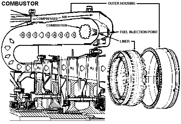
The combustion section is bolted to the diffuser section with 64 bolts. It consists of an outer housing and an inner liner which make up the 360 degree reverse annular ( ring ) flow combustion chamber. Fuel is mixed with the compressed air at 22 different points in the combustion chamber and burned. The flame continually develops the hot gases which escape out across the n1 and n2 turbines, turning them at a high rpm. The combustion liner contains louvers and drilled passageways which control the incoming air for mixing with the fuel, cooling and flame control. About two-thirds of the compressed air is used in flame control and cooling and the remaining one-third for mixing with fuel for combustion.

Generic information about the combustor section
|
|
|
|
| Updated: 12 January 2008 | Born on 20 February 1999 |