|

|

|

|
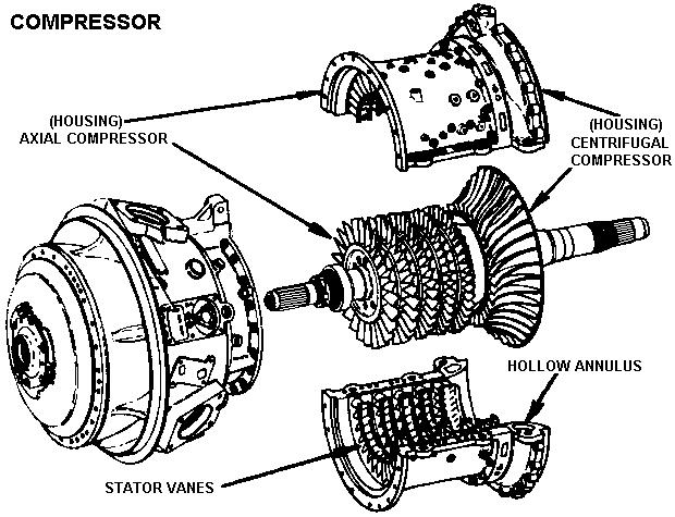
The compressor section is the second section of the engine. It consists of two external housing and an internal axial-centrifugal compressor rotor. The axial compressor housing has stator vanes bolted inside and support the component mounting pads on the outside. The stator vanes fit between the five axial compressor rotor stages to keep the air on a straight and narrow path as it moves through the compressor section. The centrifugal compressor housing is bolted to the axial housing and has a hollow annulas (cavity) where hot bleed air is stored for customer use. Internally the compressor assembly consists of a centrifugal rotor which is bolted to the axial compressor to provide five axial stages and one centrifugal stage of compression. The compressor rotor is supported by the #1 and #2 main bearings and provides 7 to 1 compression ratio.

Generic information on the Compressor section
|
|
|
|
| Updated: 12 January 2008 | Born on 19 February 1999 |